CC Evacuated Tube System

Since early October, I have been working on a test unit in my front yard that integrates geyser pumping with evacuated tubes. I had planned to write a series of posts describing the process and challenges in the chronological order, but instead I have decided to now post the current status and work backwards. My hope is that more of you will share ideas and collaborate with me on the development. I continue to believe that this is an important technology, one that should not die.

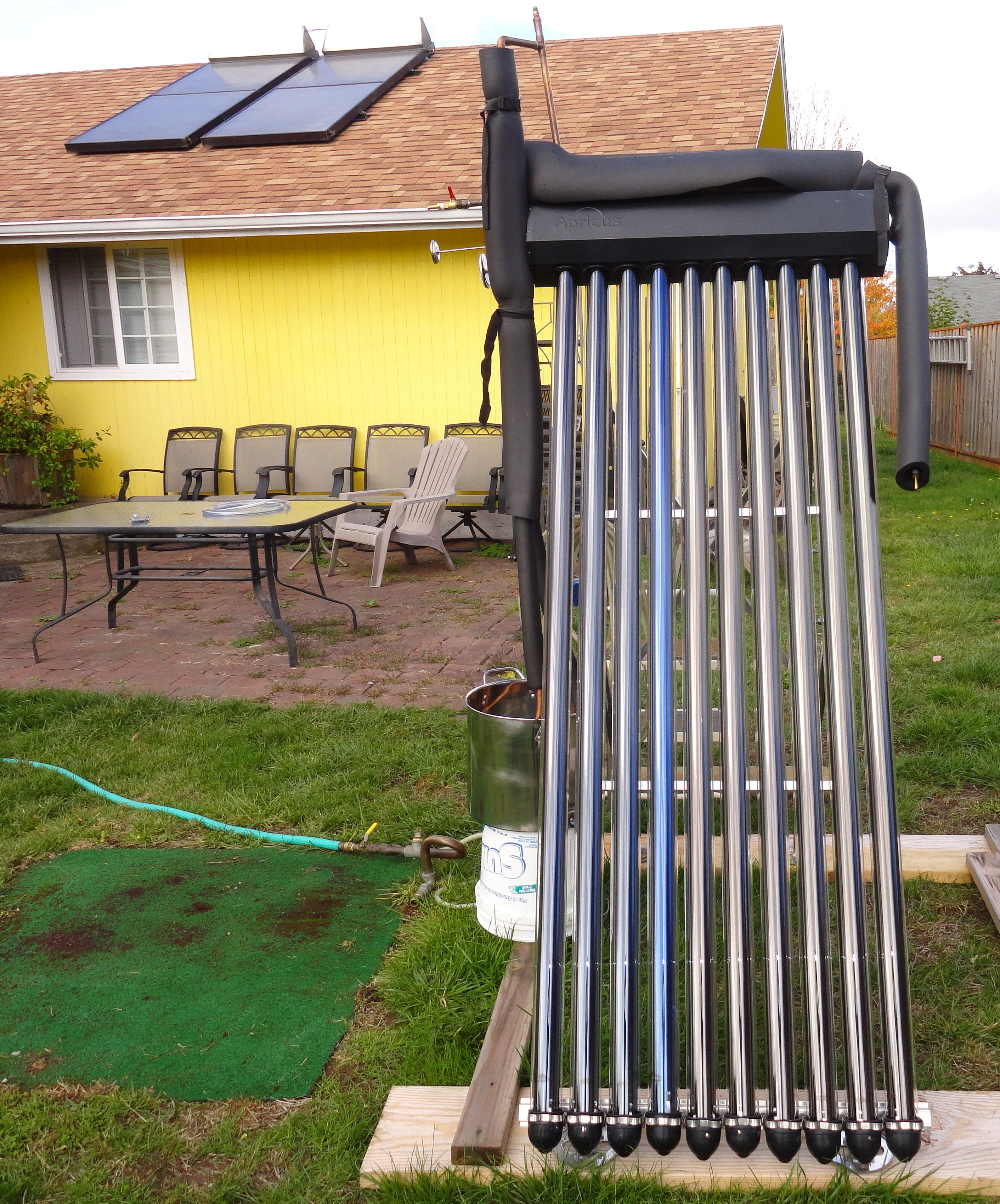
Apricus Tubes and header with geyser pump. Notice double Copper Cricket on my roof.

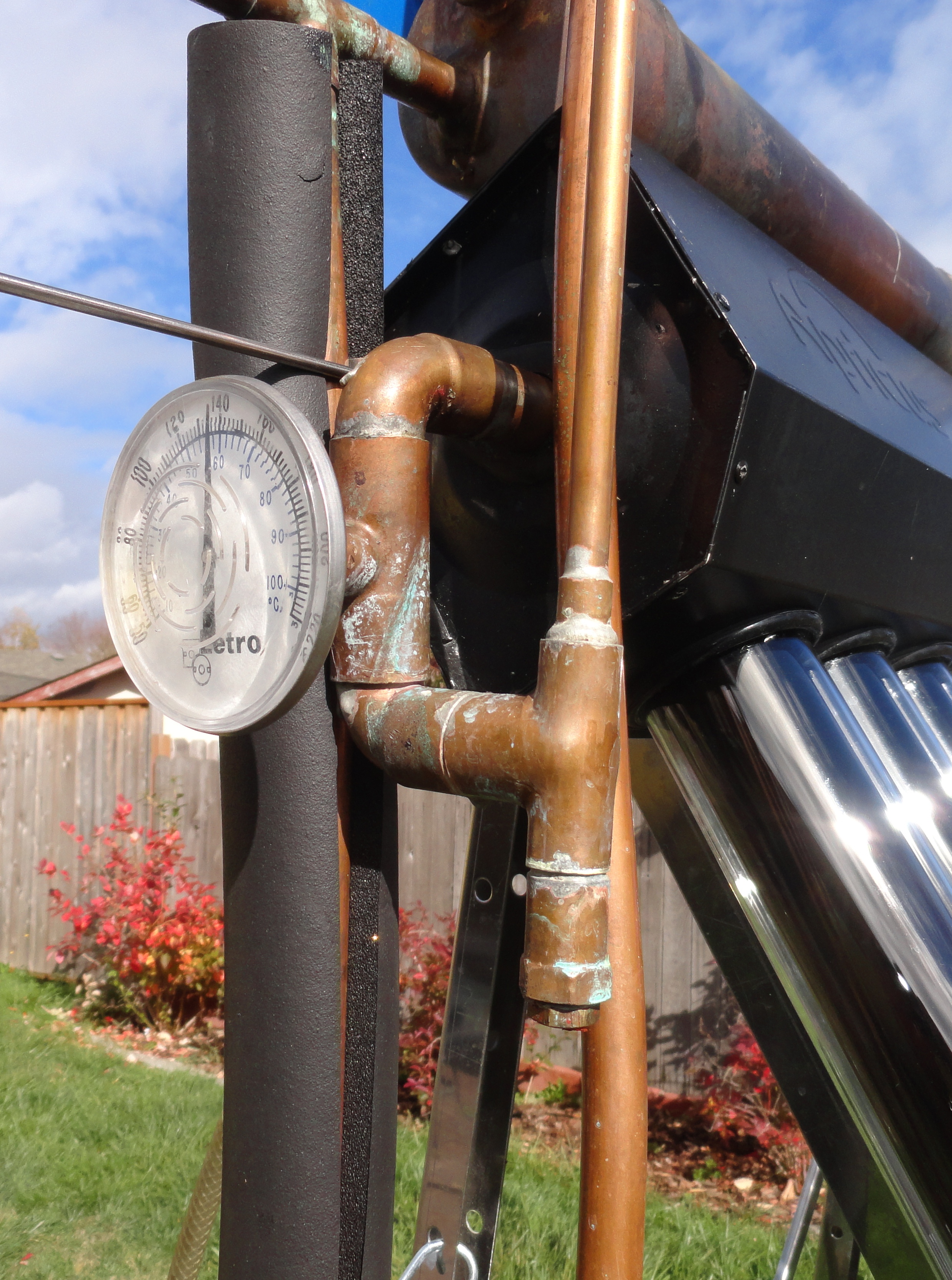
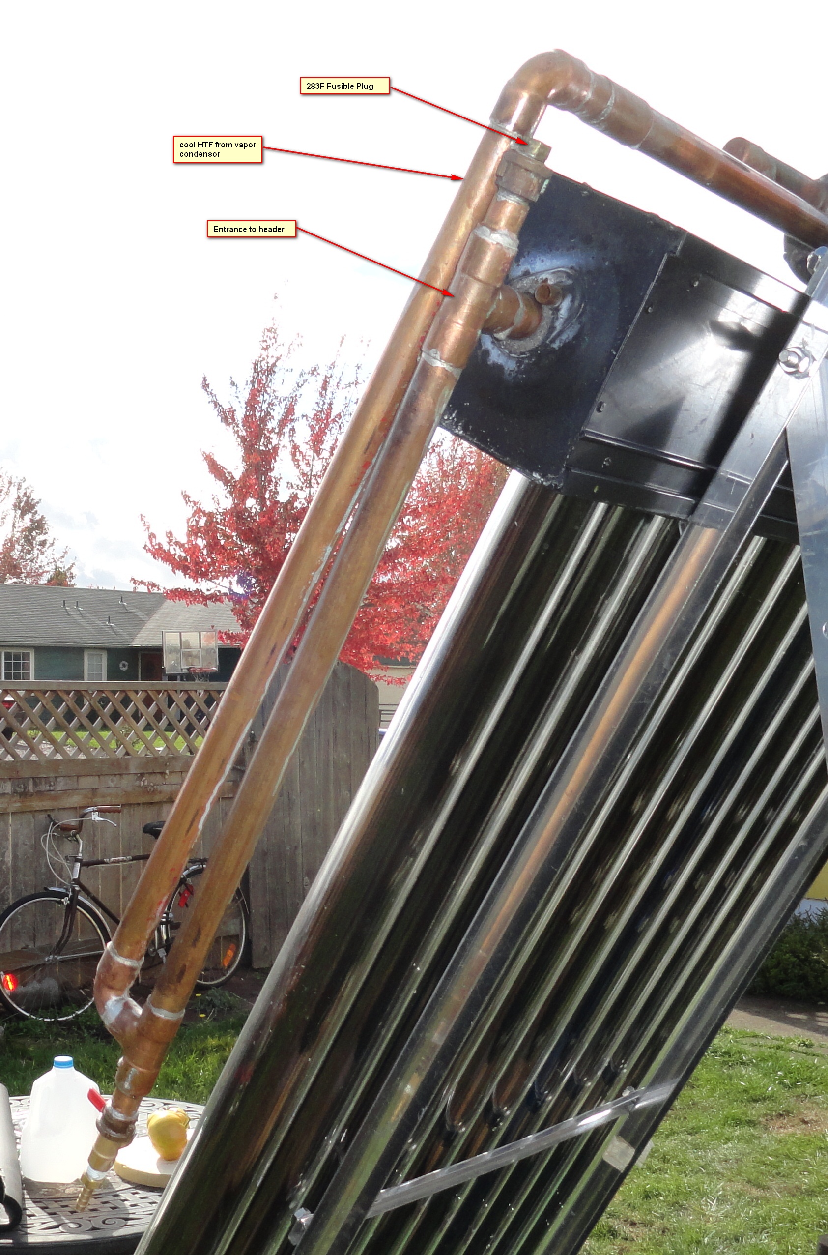
This is the second revision of this system. The first required a check valve to limit back flow. I added a vertical loop of pipe on the entrance side of the header to increase the mass against the acceleration of the steam. It worked.


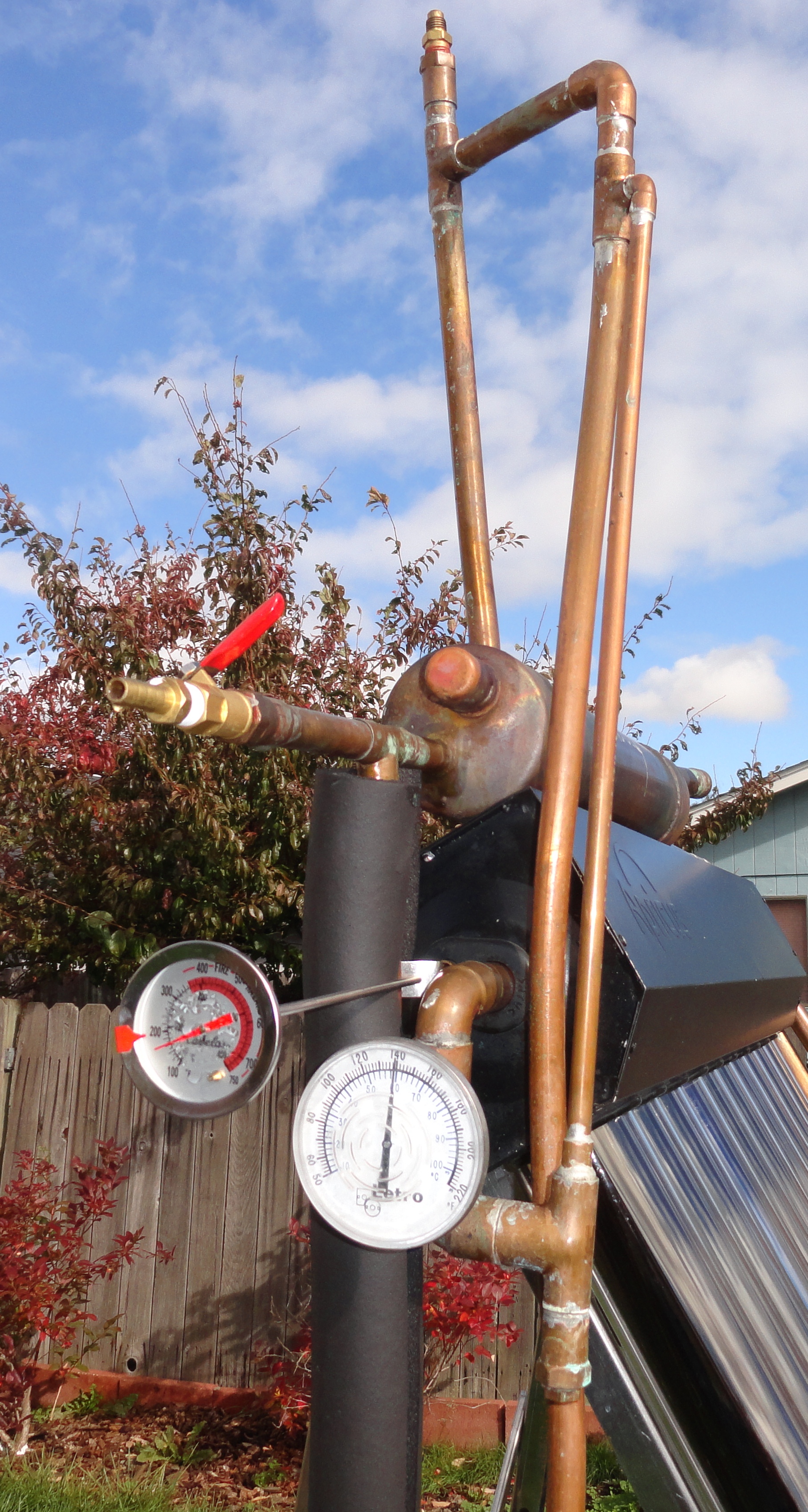
Backflow resistance loopAlso, I added a small loop on the exhaust side of the header so the steam would have to push a slug of liquid up the lifter and not be able to by-pass the liquid.

Liquid Trap

This unit pumps almost perfectly. The only problem has been that every few days it locks up and doesn’t pump. The header reaches over 350F, but it must be completely empty of steam or liquid. The exhaust temperature reaches only ~200F or less. I imagine there is a surface of liquid in contact with the 350F void that probably has a very small, balanced amount of steam pressure that refuses the entry of any additional fluid. If I either add a little bit of vacuum or release some pressure the system jumps to life with lots of gurgling and internal bashing of liquid. It’s interesting also that the fusible plug on the right side of the collector doesn’t release. Even though the header is at 350F, the pressure in the system is only a few psi, and the heat doesn’t reach the fuse plug installed just a few inches above the header.

Pump Plumbing

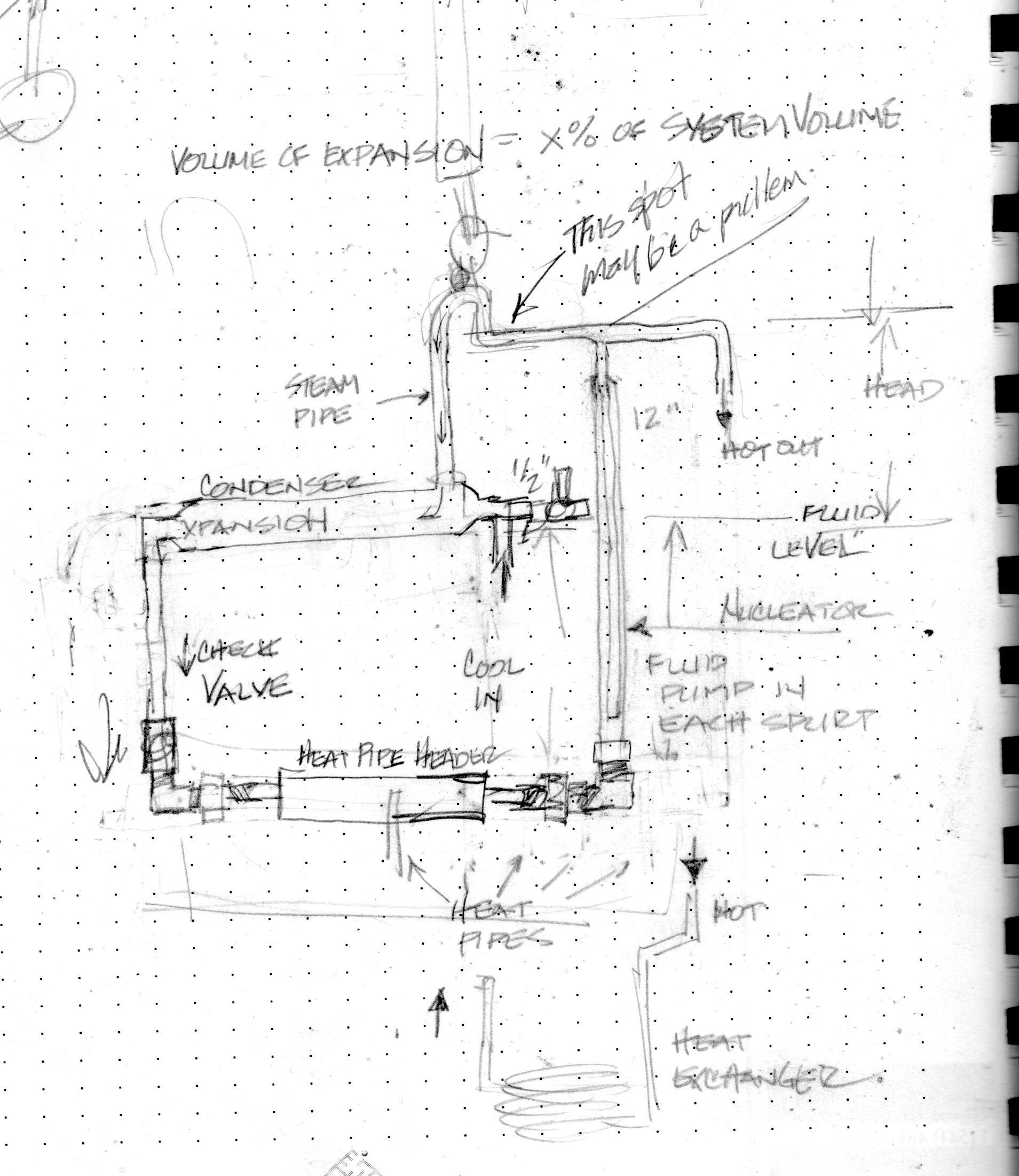
First Prototype Schematic

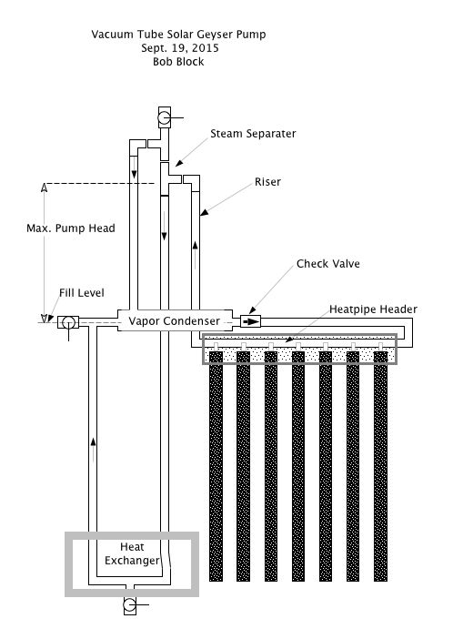
Vacuum Tube Geyser Pump Schematic

Copper Cricket V2 Open Source

The Copper Cricket was, and still is, a simple, efficient and reliable solar water heating system. Most of those I visit these days are systems on homes in the process of being re-roofed. I help remove the collector and return to replace and recharge it. Once in a while a Cricket is out of sorts. The most I have had to do is flush the heat exchanger, replace the fuse plug and recharge it.

I had been considering integrating the Copper Cricket pump (geyser pump) with evacuated tube solar collectors. I envisioned several ways of doing this, but had not built one. In 2014 Raymond Lam of Silk Road Environmental contacted me because one of his clients had a non-functioning Copper Cricket, and he didn’t know what to do with it. I met him at the Cricket’s home in Portland and recharged the system. It had over heated while the home-owners were away on an extended summer vacation. Ray was excited about the system and spent the next several months trying to build a working model using the evacuated tubes and headers that he imports from China. After hitting a wall in development he hired me to troubleshoot his prototype. I visited him at his shop and determined pretty quickly that his prototype had no chance of working. He didn’t quite understand the functioning of the system. Instead of trying to get his to work, I showed him a sketch from my notebook. I said I thought this would work, but I hadn’t tried it yet.

We rummaged through the fittings and fixtures in his warehouse and then went to the plumbing store to buy the rest of what we needed. We started to assemble the prototype that afternoon. I have to say, I was amazed at how quickly and easy it was to assemble his 20 tube evacuated tube collector.

That night in my hotel I sketched the details of the prototype we would complete the next day. By 1pm we had completed the fabrication of the system and filled it with water. It pumped immediately, and I was able to track the rapid flow of heat through the uninsulated system. I suspected that the system would not hold a vacuum due to some of the odd fittings we had to use, so we let it run with the evacuation port open to the atmosphere. I didn’t try to measure the pump rate, but it was clearly fast enough to move fluid through the system, and very little steam was escaping the evacuation port which indicated that the steam was condensing internally.

Ray has decided to move forward with a proprietary revision of the system, so I agreed not to post photos of the one we built at his site, but I told him I was I would continue to move forward on my own and publish the geyser pump solar water heater as an open source technology.

Crickets looking for new roofs

Friday, I picked up 6 complete Crickets from Solar Assist in Eugene, Oregon. They were about to scrap them. I now have 4 heat exchangers, too. Also on Friday, someone in Eugene called and said he had a Copper Cricket in his garage and was wondering what he should ask for it to sell to his neighbor. 

Homeowners are removing the collectors to re-roof and can’t justify the expense of re-installing them. It’s a strange statement about the change in values from 20 years ago. Many of the homeowners removing the systems are not the original owners. I can see their point. In Eugene, we still pay less than 6 cents per kWh. A new tank now costs about $400 and a typical re-install and fill costs $600-$800. At about $100 savings per year, that’s a 10-year payback. That’s about the payback of a new system when these were sold with tax credits and rebates in the ’80s.

Installers now urge homeowners to buy heat-pump water heaters. They have a much easier installation, and we’re told that they have at least a 10-year life-expectancy.

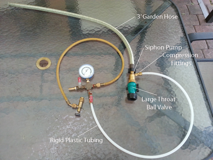
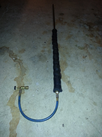
Cricket Vacuum Charging Apparatus

I’ve always disliked the MityVac hand pump, but it was all we could find at the time. Before that we used a very expensive siphon pump that we sourced from a steam fitter catalog. About a year ago, Eldon told me about a garden variety siphon mixer that he had used to evacuate his system. I bought one and have been experimenting with it. I consistently get vacuums at 29″ in just a few minutes using this pump and city water pressure.

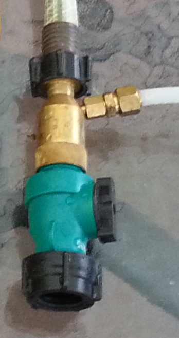
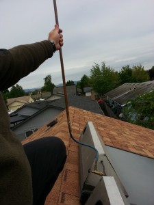
The Hozon Brass Siphon Mixer is idea for this use if you make a few modifications. I used compression fittings to attach the rigid plastic hose for an airtight seal. I also used a large throat ball valve to increase flow at siphon. The 3′ of garden hose at the end increases the vacuum by a few inches by not letting air back into the pump. On a tall roof, I used a long garden hose as a secondary siphon to pull the water back down to ground level thereby increasing the relative pressure at the siphon mixer.

The Hozon Siphon MIxer is available at

http://growerssolution.com/PROD/brass-siphon-mixer/siphon-mixer

This is so much easier than the hand pump. Drawing down my empty two Cricket system to 29″HG took only 10 minutes. After filling the system with water to the correct level it took only 1 minute to draw the cold system down to the point that the collectors started pumping.

Here’s a closer look at the siphon mixer in my apparatus. 

Leaks and Leaks

The bane of the geyser pump has always been leaks. When I met Eldon, he and Don Ladigan were working on a prototype. They had attempted to make the header/riser connections with brass braze on copper and fill in the gaps with solder. It didn’t work.

After we learned silver-brazing things got easier, but we still eschewed any possible loss of system integrity.

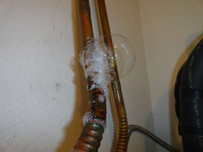
Fast forward 25 years: The system on my home, the first prototype of a double CC system has been failing for several years. I could get it going for a few weeks, but then it would over heat and stop. I checked every fitting several times and even opened up the collectors and tested them. I couldn’t find a leak. Eventually I went for broke. I filled the system with water and let it over heat and over pressure. I stripped off the insulation looking for a coupling that may have been hidden in a straight pipe run, and found some wet insulation. The copper pipe was discolored. But I couldn’t see where the water was coming from. I emptied the system, pressurized it with air, and sprayed soapy water on the pipe. Withing seconds it flowered into a dozen soap bubble mountains. 


I couldn’t imagine what happened. We believed the methanol solution to be safe from acidification, so I surmised that it must have been the pipe. I removed 30′ of 3/4″ soft copper tubing from my attic. I attached caps to the ends and an air fitting and pressurized the two lengths of pipe. There were pin-hole leaks over the entire length of tube. There were no leaks other than in the soft copper tubing, and there were at least 15′ of rigid copper. It must have been the soft tubing.

I replaced all of the soft tubing with rigid tubing and elbows. Last Thursday starting at 5AM before the attic heated up. The plumbing went well, and I finished up the 26 solder joints at 8AM. I had a cup of coffee, and then pressurized the system to 120 psi with air. I couldn’t get the pressure to hold, so I looked up at the collectors and noticed that I had left the fill valve in place and open. Doh! I hopped up on the roof and closed the valve. The system then pressurized to 125 and held, but after an hour it had lost about 5psi. I figured that with 26 joints there was a high probability that I has a leak in one.

This morning, Saturday, I decided to hunt down the leak. Again starting early, I went into the attic with my flashlight, mirror and soap sprayer. I dowsed every fitting and there were no leaks. I removed all of the insulation remaining on the rigid pipe: no leaks. I went into our laundry room where the tanks reside and tested the new fittings coming through the ceiling: no leaks, but then I heard a fizzle in the insulation below the new fittings. I removed the insulation and found more leaks.

There were bubbles emanating out of the entire 2′ length of the flexible connector.

So it wasn’t the soft copper. This is a completely different piece of copper from a different manufacturer.

NEW THEORY: The methanol solution turns acidic when it sits for a long time in the presence of air. I had left my system sit for about a year after it blew its fusible plug. I’m sure it blew all of the fluid out of the collectors and a lot from the pipe runs. The soft tubing that failed was almost completely horizontal, so as it evaporated, the air interface probably moved down the length of that pipe.

A year later I tried again, and failed but I drained almost all of the fluid from the system. I remember there being more fluid in down near the heat exchanger when I blew air in to pressurize it. I left the fluid in for several months before completely draining the system. I’m guessing that the fluid was up in the flex connector and ate its way through. The other flex connector didn’t show any signs for leaking, so I left it in place. I plan to activate the system again with pure water for  a few weeks before filling it with methanol again. That will flush anything out that shouldn’t be there including the flux from the soldering I just completed.

Double Cricket System For Sale

A Cricket owner contacted me and says he’s got an in-the-original-box Double Copper Cricket system for sale. It was intended to go on his house 20 years ago but sat in his garage instead. He now wants to sell it and is asking $2995. It’s in Redding California. Contact Bob Block for more information bob@soloregon.com.

Sun Start Refined Apparatus

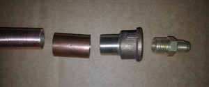
I rebuilt the Sun Start Chimney pipe with a little more patience and time spent scrounging my garage for better fittings. I was able to find a bronze adapter, but a less expensive piece would have been a 1/2″ SWT to 1/4″ FPT copper fitting. I sweated this together and wrapped it with a few feet of high temp pipe insulation. I also inserted a loose plug of copper scouring sponge down the pipe to reduce fluid loss. I’m looking forward to another sunny day to try it again with the insulated version.

(October 1, 2013) I’ve since told Eldon Haines about this and he built his own out of three-quarter inch copper pipe. I think this is probably advantageous, but we didn’t have enough sun to test it and I haven’t heard from him whether or not it worked. My guess is that it will work better than the half inch pipe because less fluid will be ejected from the end of the pipe. I also found that it does take quite a while for the system to heat up to above atmospheric pressure after you stop the flow through the heat exchanger on the domestic side. The system still has to heat the water that is in the domestic side of the heat exchanger, about a gallon, and that takes some BTUs.

Chimney-pipe parts

Parts


SunStart Chimney Pipe Refined and insulated

New Sun Start Technique

Sun Start Chimney Pipe

Sun Start Chimney Pipe for charging Copper Crickets without a vacuum pump.

For many years we theorized starting Copper Crickets using only the heat from the sun. We never really got it to work, and certainly never recommended purely sun starts to our customers or installers. I’ve been working on my own double Copper Cricket system, and was having a hard time evacuating it with a hand pump because I have ‘trigger fingers’, two on each hand that make using the hand pump painful. Yesterday I thought of a better way. My system was over heating because it had air in it. I went up on the roof and carefully attached the actuator valve, evacuated the line, closed the ball valve between the hand pump and the collector to protect it from heat, and opened the actuator. Sure enough, there was over 20 psi of positive pressure. That means the system was over 230F. I took a male 1/8″ SAE fitting and silver brazed it to the end of a 4′ piece of 1/2″ copper pipe. I was in a bit of a hurry and burned a hole through the brass fitting, so I had to fix it with more silver braze. It ended up being quite ugly. I took this to the roof with a short refrigeration hose and attached it directly to the actuator valve. I put on a pair of leather gloves, and holding the pipe vertically, I opened the actuator valve. The steam flowed out of the pipe, and any liquid that bubbled out, just stayed in the pipe and flowed back down. It took just a few minutes for the system to return to atmospheric pressure. The long pipe condensed a lot of the steam, returning the condensate to the collector. I’m sure I didn’t lose more than a few ounces of liquid. I closed the actuator and sealed it with the cap. The Delta-T of my system was better than ever before, and I was able to charge the system in full sunlight in a matter of minutes. I’m going to experiment with different larger diameter pipe and different conditions, but this really seems to work well.

I have a few local Crickets that need burping. I’m going to open them up and let some air in. Let them overheat and gain pressure, then attach my charging chimney and let them drive out the air. We’ll see if that does the trick.


Dyer Restart in Bend Oregon – October 27, 1012

Lance Dyer first contacted me in August. I stopped in to see his Cricket while returning home from a camping trip in Bend. His Cricket had stagnated because the house had been in foreclosure for over a year. The house plumbing had been ‘winterized’ leaving no water in the solar tank. When they took possession of the home, in the Spring of 2012, the Cricket was not working. Lance called around to local solar companies and they recommended swapping out the 20 year old system for a new one. He found my Web site and connected me the day before I was leaving to camp within 5 miles of his home.

Upon my arrival he already had the ladder in place. It is a first story installation only a few yards horizontally from the storage tank. A standard two-tank system with two 50 gallon electric water heaters. The fuse plug had blown, but no other damage was apparent. I told him I would return with a charging kit. My charge was lodging plus $170. The Dyers also fed us lunch, dinner and beers while we watched the Ducks play. All in all it was a very pleasant vacation.

They lodged us (Elizabeth came with) in a nice Best Wester motel in Sisters.

We arrived Saturday at about 12. Here’s what we did.

  1. Install fuse plug with RTV
  2. Install drain valve – I didn’t remember that the second generation Crickets used ¼” drain valves. Luckily I had brought a bag full of spare parts and used many of them throughout the day.
  3. Pressurize system to 110PSI. I needed a yellow jacket hose with a tire type schraeder valve. The system held pressure.
  4. Mix the Methanol. 4 gallons of distilled water, 1 gallon methyl alcohol in the night start tank. I plugged it in, and the temperature went immediately to 95 degrees F. I thought the tank was working although very slowly. We went to a pub to watch the end of the Ducks game, but saw only the last touch down of a 70 to 14 emasculation of the Buffalos. We returned.
  5. Check the pressure. Still at 110 PSI. There was some fluid in the heat-exchanger so we installed the actuator valve and hooked it to the long evacuation line and let the air pressure drive out the fluid. Then we evacuated from the bottom of the system for a while. The gauge read 21 in hg. Not quite enough, but I thought we might be able to achieve a sufficient vacuum if the fluid was hot. The fluid in the night start tank was still at about 90F when we returned. Clearly the tank was not working and the raise in temperature initially was caused by the exothermic reaction of the combination of the alcohol and water.
  6. After a bit of work, I determined that the thermostat switch on the night start tank was not working and clicking out at about 100F, so I wired the element directly to the power cord. The tank heated to 160F within 20 minutes. I referred to this as hot-wiring the bomb.
  7. I removed both Schrader valves, top and bottom, cleaned the orifices with a pipe cleaner and replaced them with new vitol valve stems.
  8. I noticed that the vacuum assemply gauge was not working  and some of the connections were leaking. Also, both of the actuator valves were inoperable. One was bound, and the other would not depress the valve stem. I happened to have one of my own that did work, and I also had a replacement gauge.
  9. I evacuated the system at the roof an achieved about 23 in hg.
  10. I connected the drain port of the night start unit to the schraeder valve at the heat exchanger and let the fluid fill the heat exchanger.
  11. The fluid reached a height of less than a foot with the hot fluid and the poor vacuum so I pressurized the night start tank to 30PSI. The system filled. I kept the evacuation going until fluid ran into the evac hose. I turned the vacuum on and off for a while until I was certain the system had been completely filled. I let fluid drain from the drain port, opening the evac system to atmospheric pressure. I added about a pint back into the system.
  12. I evacuated the system to 20 in hg. Removed the evacuation device and put away my tools at just about dark, ~6:30 PM.

Sunday:

We returned to the collector on Sunday morning and checked the vacuum. It remained at about 20 in hg. I would have thought it would have been lower since the system had been hot the night before. But, the evacuator was not able to pull more of a vacuum than that, and it still leaked a bit, so I drew as much of a vacuum as it would draw. The sky was very dark with a bit of rain.

  1. We uncovered the collector.
  2. I drained the excess fluid from the drain valve, replaced the ¼” plug with RTV sealant. [ I don’t think applying RTV to a wet fitting is optimal. I think it would be better to drain a bit more from the bottom of the system so the threads of the drain port could be dried with a rag, or heat. Applying heat from a torch to a cold system should not be dangerous. ]
  3. I added a bit of fluid into the evacuation port, and re-evacuated the system to 20in hg. I could do no more than that.
  4. Elizabeth and I went shopping for a few hours hoping that the sun would come out, but it didn’t. So I packed up all of the tools.
  5. I bought a 4” pvc knock-out plug at Home Depot to replace the lost plastic hood port. I think these are probably a little more durable, but they need to be glued in with RTV.

[The access port in the hood is too tight to get the evacuation actuator valve in comfortably. The hood port should have been cut an inch to the right to allow more room for the actuator and replacement of the fuse plug.]

NIGHT START TANK

I think the idea for night start was in the right direction, but the tank seems to me to be unwieldy and dangerous.

  1. The tank still has a sacrificial rod in it. Why? When I drained the tank there were bits of white crumbs in the fluid. This has potential to introduce some ongoing reaction in the fluid. [Could this be the cause of the internal corrosion that stopped Eric Thurston’s system at the fluid surface near the top of the down-comer?]
  2. How much time is required to drive out the air from the fluid? How much is removed just by the combination of the alcohol to the water? Heating and evacuating the tank has the potential for dangerous discharges of hot methanol.
  3. Pressurizing the hot tank adds more danger. I didn’t release the pressure from the tank after we finished filling the collector and accidentally opened the funnel valve after setting the unit into the back of my car. It shot fluid and air into the air with a lot of force and sprayed near my face.

NIGHT START IDEA

Rather than using a water heater, use an on demand water heater and small pump to circulate near boiling water in the domestic side of the heat exchanger. Fill the collector system from a bag of pre-mixed fluid from the bottom using another small electric pump, while evacuating the system from the collector.

This would allow any air to boil out of the system while is fills and comes into contact with the hot heat exchanger. The fill pump would have sufficient pressure to drive fluid past any vapor traps, while the heat would force the vapor out of the heat-exchanger.

The hot fluid would fill the cold collector, but would already have release its trapped air. The only air left in the system would be the small amount trapped on the inner surfaces of the nucleators.

A RETURN TRIP.

I told the Dyers that their system would probably run, but it would not be very efficient with such a poor vacuum. I would have to return or send them a vacuum pump. I think it’s best if I return with a vacuum pump and do it myself.

All that might be necessary is to draw a vacuum on a sunny day with the system already at a temperature about 160 but not quite at atmospheric temperature.

Two reasons we were not able to draw an adequate vacuum were that the water pressure/volume to his hose was inadequate and there were leaks in the evacuation system. There was a four connection ball valve on his water outlet. That might have been too constricting for the vacuum pump on his 50′ of hose.

THERMOMETERS:

On the systems I have worked on in the past year, I have found that the inclusion of just one thermometer is a hassle. All three thermometers are necessary to determine of the system is operating. Since the Letro thermometers are so expensive. I am going to try to use cheap digital thermometers attached to the outside of the copper tube. Ideally these would be glued to the pipe with silicone and insulated. The digital thermometer stems could be bent 90 degrees to allow for a solid connection and ease of viewing. I am going to test this on my systems.

For testing purposes a set of 4 digital thermometers attached to a data acquisition using would be very helpful. If it could connect via Bluetooth to an Android pad, the system could be very closely monitored and analyzed.


Valve Insight

I received a call today from Rich Baker in Massachusetts who is working on a crippled cricket. It has an  estimated 40′ run between the collector and the heat exchanger, and the solar pad / solar tank has been replaced with an electric water heater with an internal heat exchanger.  He said the system worked for a few days, but then quit. What really amazed me is that they were able to swap out the heat exchanger without draining the solar side and evacuating the system at the collector because there were valves on the solar loop that isolated the heat-exchanger from the solar loop. At first I shuddered. You can put a valve in this evacuated system. Every time we tried the valve leaked. But then I realized that with at least 35′ of fluid above the valves, the valves are never under a vacuum, they are most likely under pressure, so even if they leak, no air will enter the system other than air that might dissolve into fluid exposed at a leak. So, why not install valves down by the tank on really tall systems? How about 3-way valves that could direct heat to something else, like a second tank, a cooling fin for overheat protection, a kitty litter heater, etc.

Thanks for the call Rich. Good luck getting this system back on lin